Battlebot
As part of a broader Mechatronics course, I worked in a team of three to design and operate a remote-controlled battle-bot for a “multiplayer online battle arena” style competition, involving two teams of robots trying to capture the other team’s base by dealing damage to it and the other robots. The robots were operated via remote-controllers we built ourselves, but had to autonomously:
Detect a successful hit of the weapon
Detect a healing LED and distinguish between the correct healing frequency and several decoy frequencies.
Communicate with a base-station reporting health, damage, status, etc.
Mechanical design
The mechanical design for the robot was done largely by Terry Kientz, the director of the GRASP @ PERCH machine shop, who was finishing his MSE in robotics at the time by taking this course.
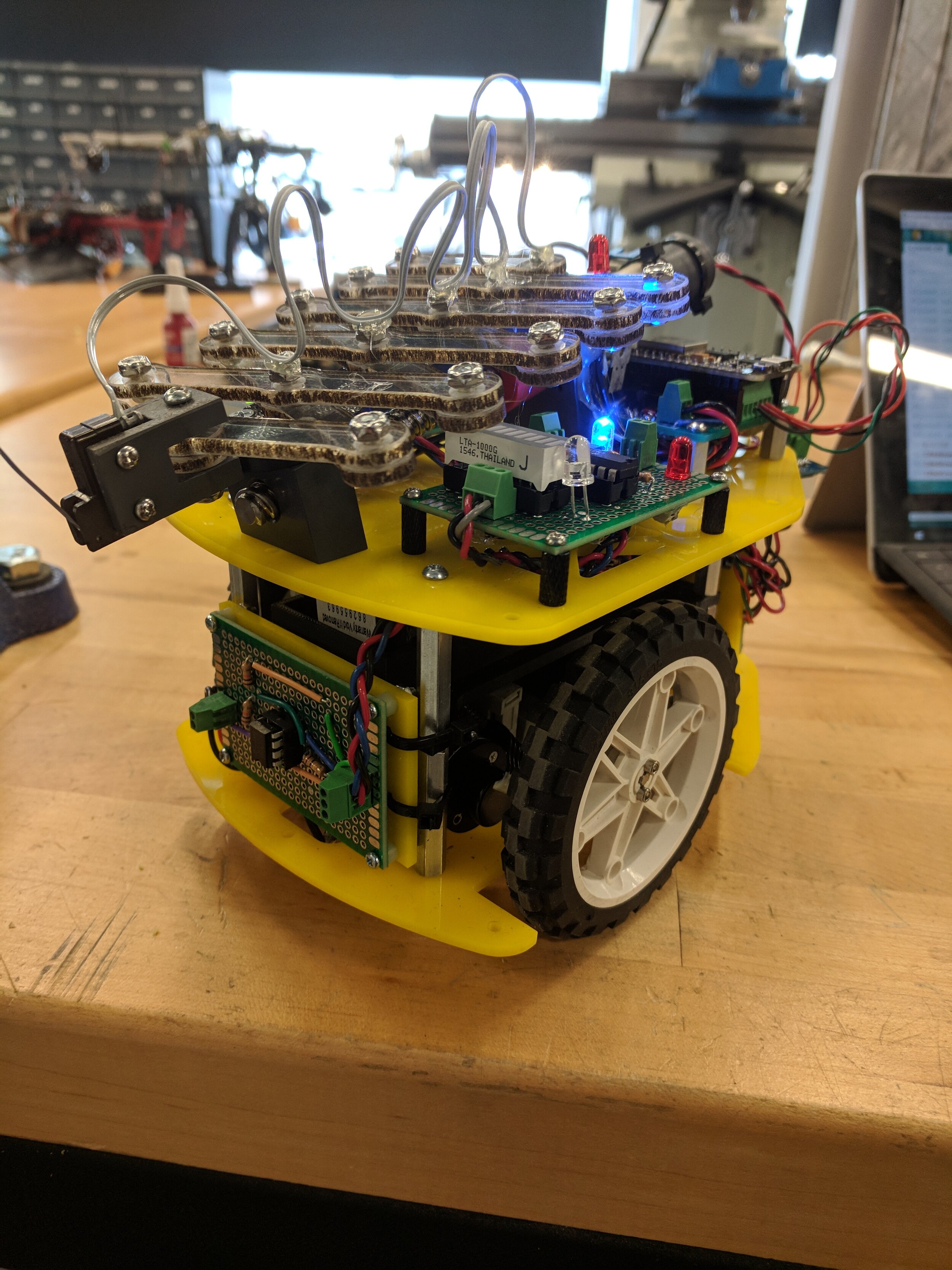
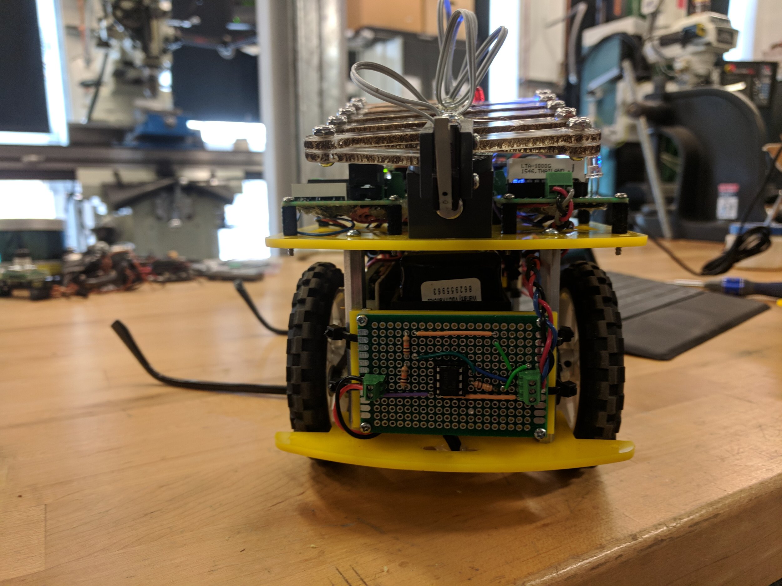
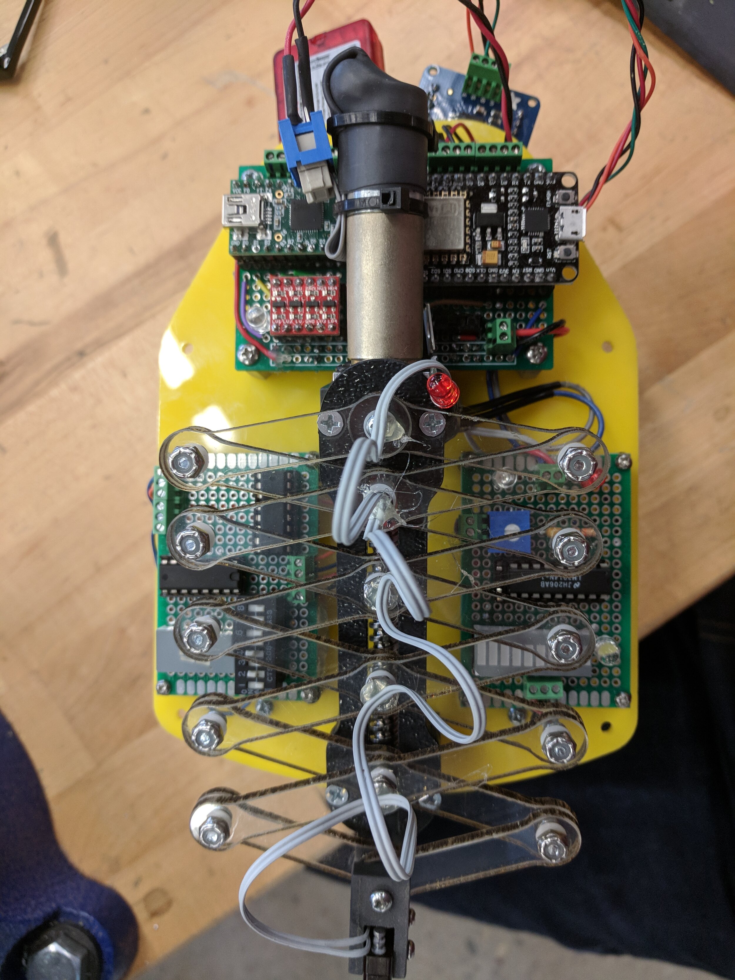
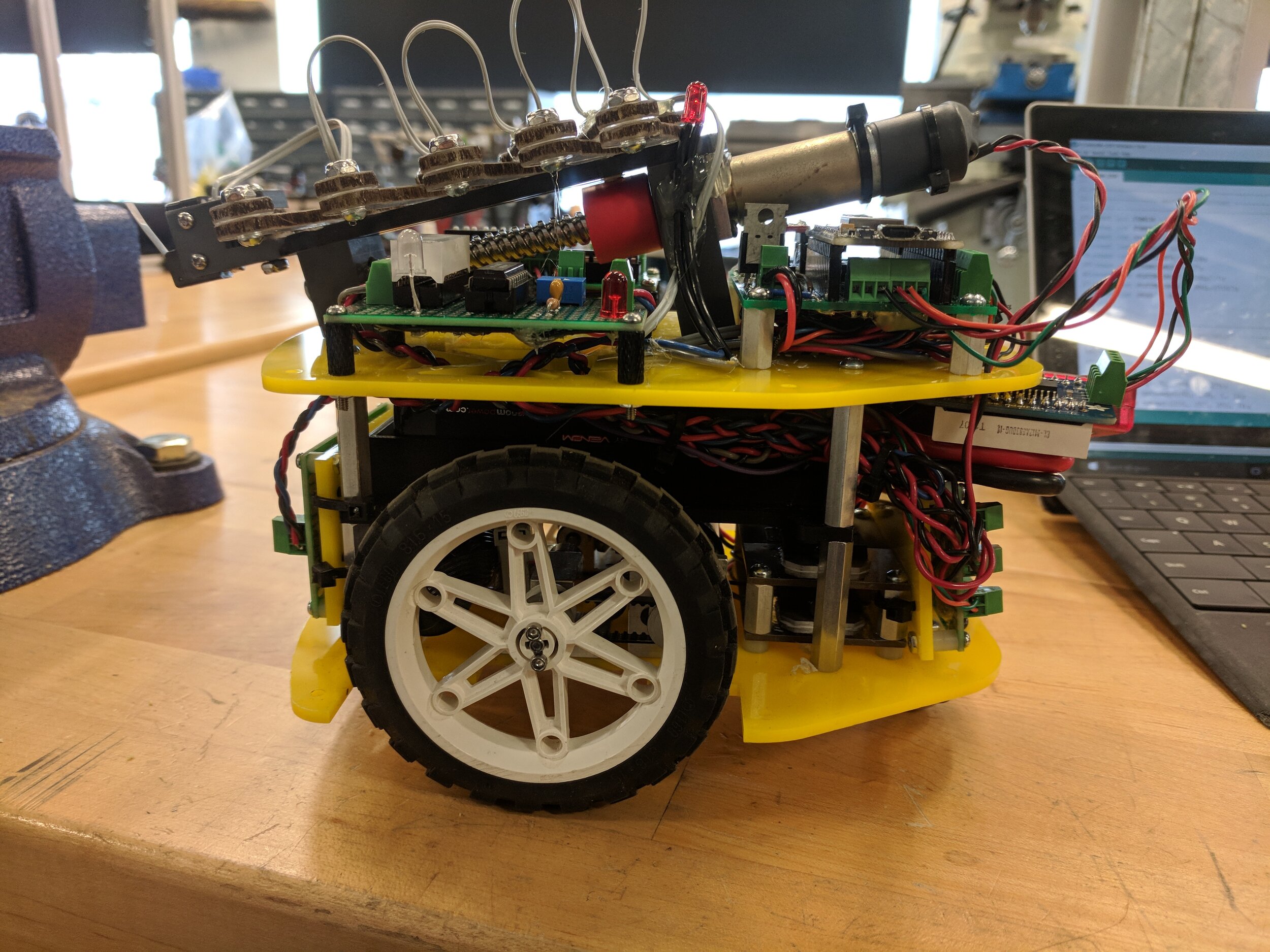
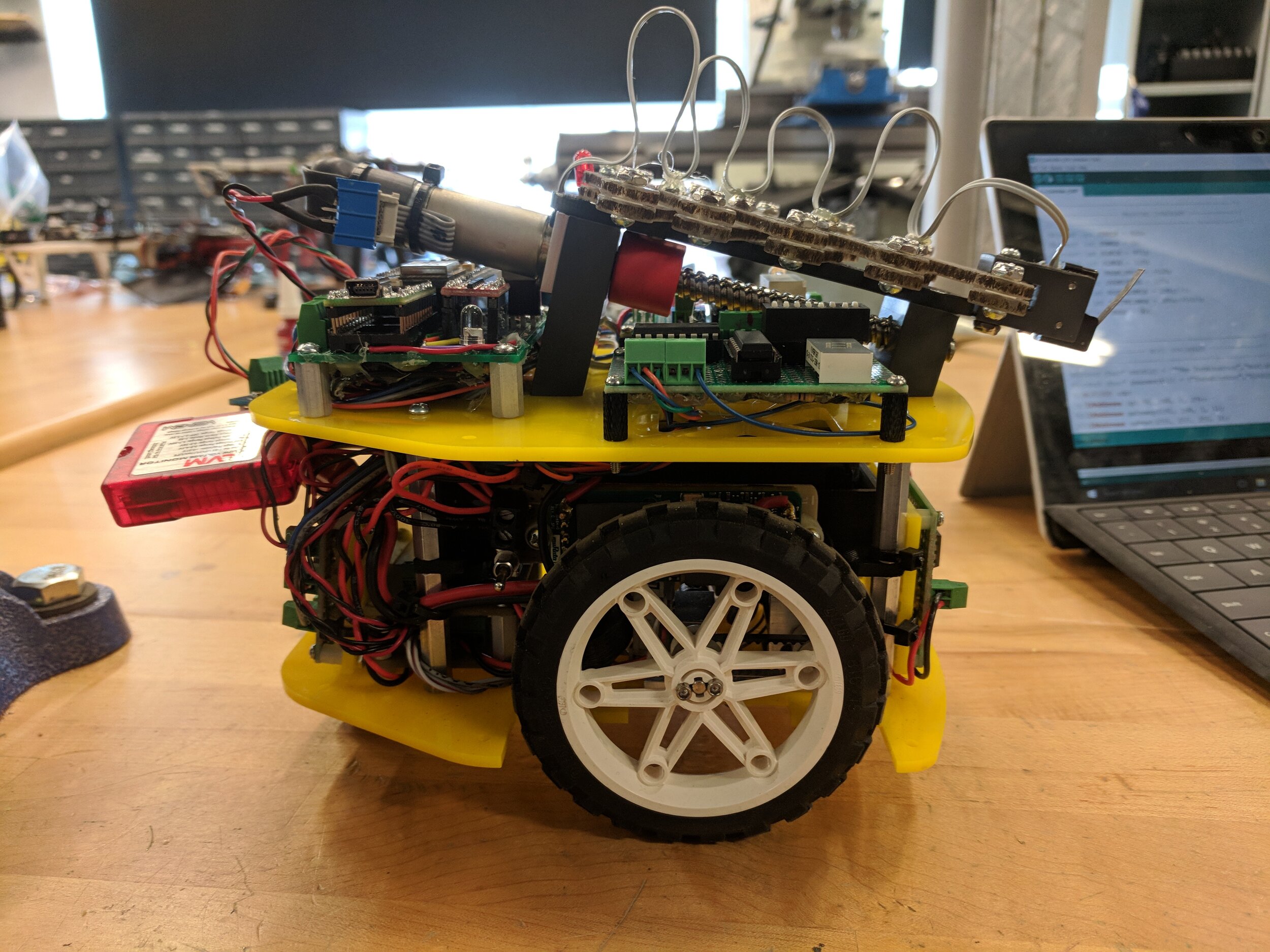
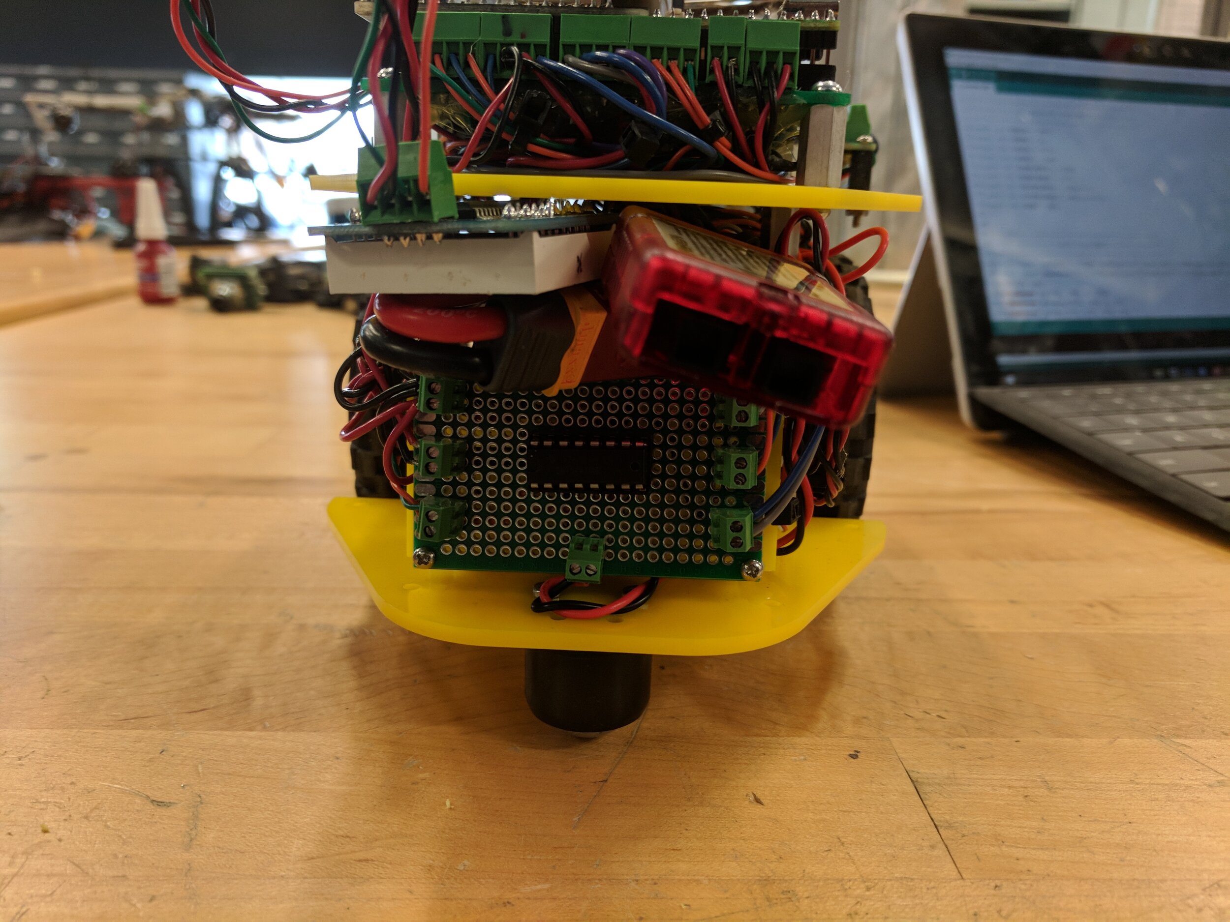
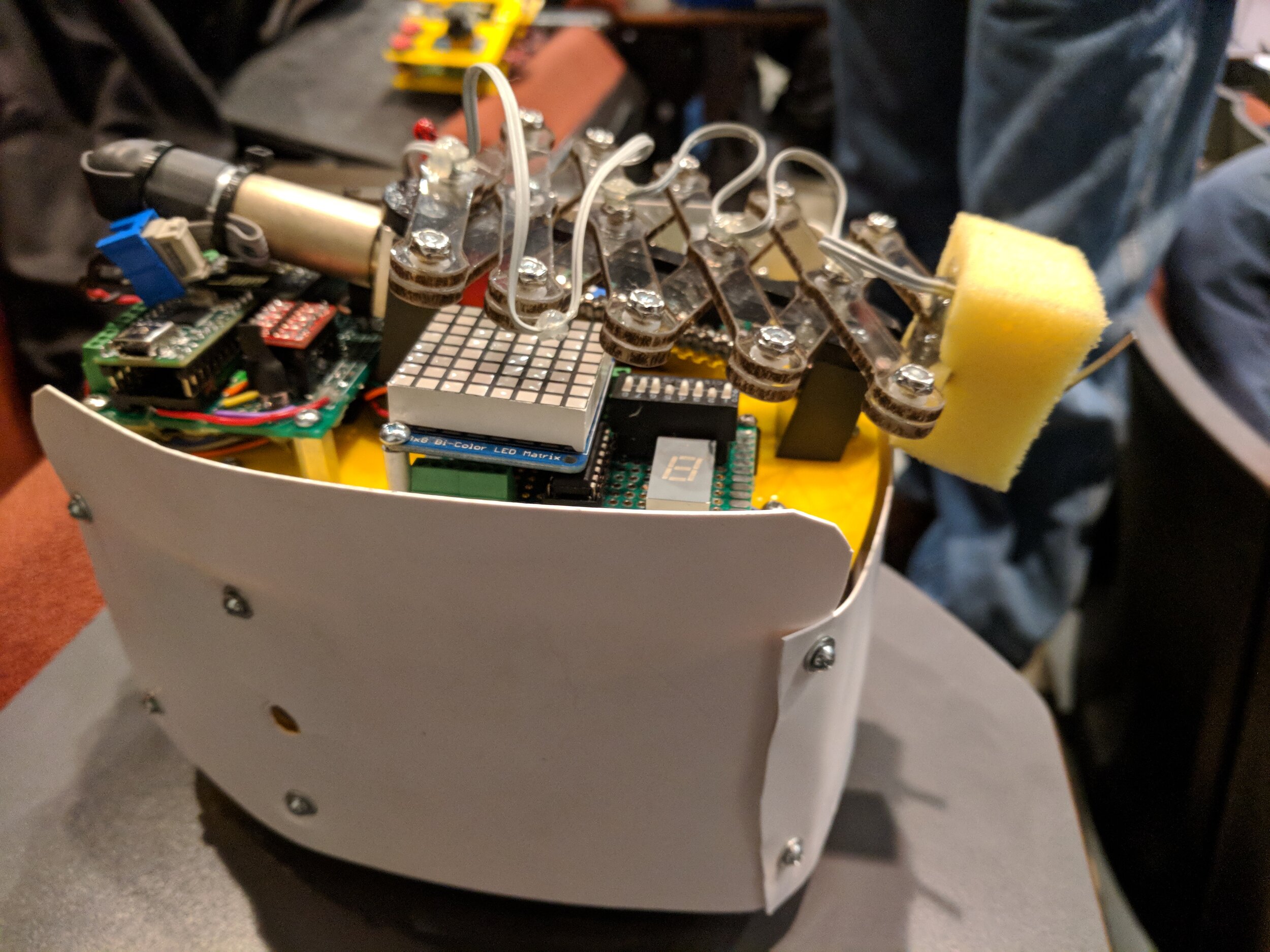
The body of the robot was built from laser-cut ABS plates, with standoffs providing separation and mounting locations for the various electronic components. Two Maxon motors powered two front wheels via Kevlar driving belts for differential drive steering, while a caster at the back provided support. A single Maxon motor on top powered a scissor extension mechanism to function as a “spear” for striking other robots.
Our design was generally successful and competed quite effectively, but it suffered from several drawbacks:
The Maxon motors used for the wheels were too powerful for the robot design. While this power made climbing ramps effortless, it made the driving motion hard to control due to the high speed produced even at the lowest inputs, as can be seen in the videos below. The jerkiness that results from this power also threatened to flip the robot on multiple occassions.
The Maxon motor that drove the scissor mechanism, on the flipside, was too slow. Our weapon extended relatively slowly, limiting the usefulness of the scissor mechanism; it was much easier to strike by leaving the weapon somewhat extended and driving at the target.
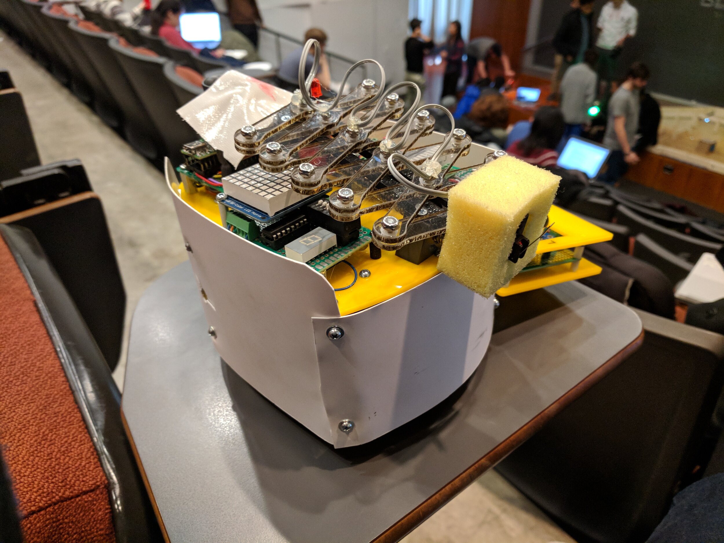
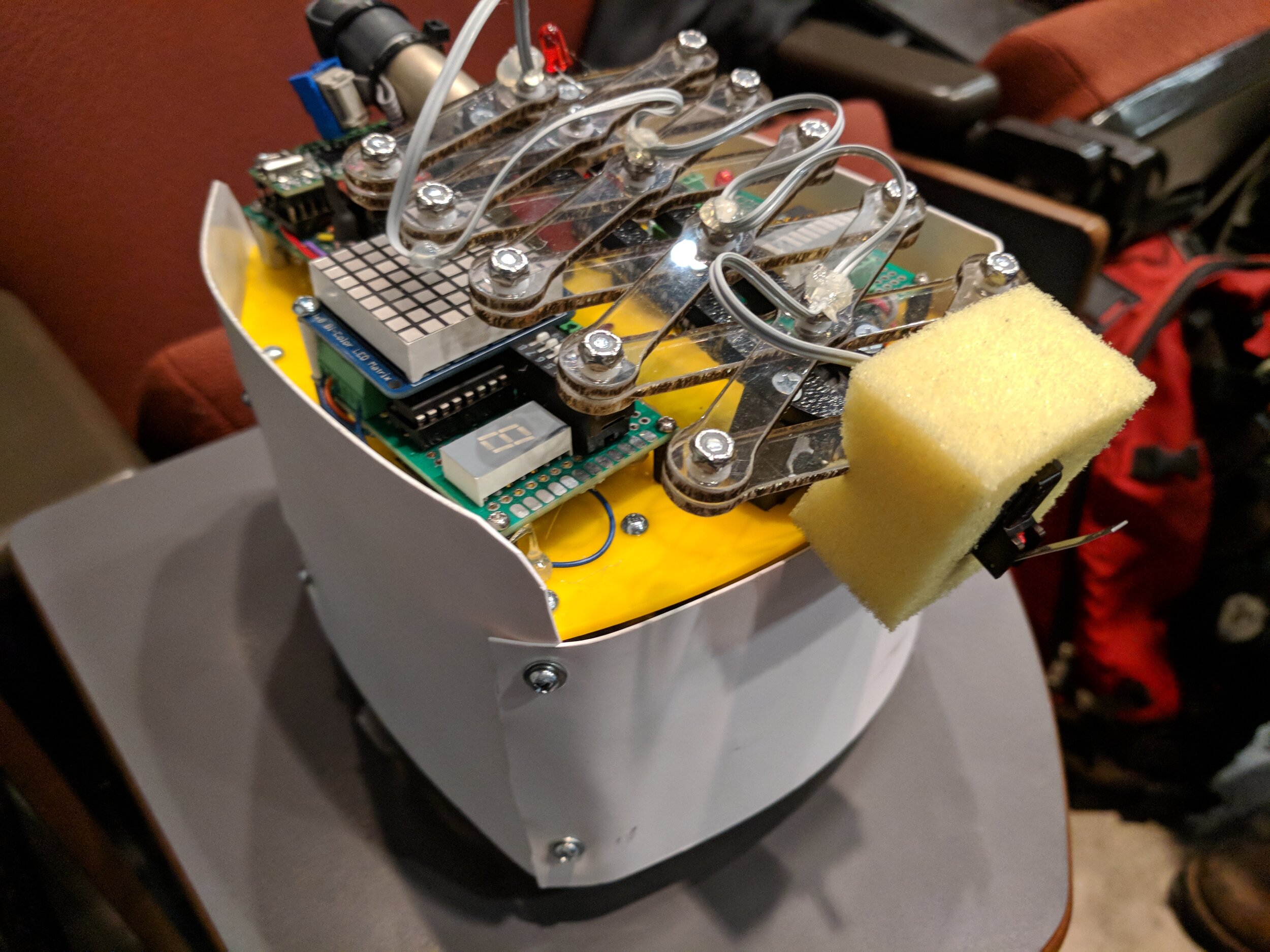
The pin-joint mechanism that connected the hit-sensor to the weapon allowed it to rotate on impact, rather than depress the switch. We were able to overcome this limitation by adding a piece of foam around the hit sensor to prevent this rotation, as can be seen in some of the later photos.
electrical design
The electrical design for the robot involved coordinating interactions between two microcontrollers, three motors, and an array of sensors. A single NodeMCU ESP8266 handled Wi-Fi communications with the controller and base-station and broadcast instructions over SPI to a Teensy 2.0, which directly controlled the motors for driving and weapon control, ran a health-bar and team-color display, and powered the healing LED and weapon sensors. A second NodeMCU ESP8266 ran the remote control, reading from two joysticks and several buttons and transmitting commands over Wi-Fi to the robot.
The processor architecture is shown in Fig. 1 below, and was designed to play to the strengths of each processor. While the ESP8266 is faster than the Teensy, its on-board architecture uses most of the GPIO pins, leaving it very limited externally. The built-in Wi-Fi, however, is a very powerful communications tool. Thus the limited GPIO was devoted to an SPI connection, while the core functionality was limited to Wi-Fi communications and high-level signal processing. The Teensy, on the other hand, has nearly complete access to all of its GPIO through bit-mask level settings. We therefore chose to devote its resources to low-level control of each of the external components. For the controller, external components were limited to joysticks and buttons only, so the ESP8266 was tasked with both low-level interfacing and communications to save space.

Processor architecture for the battlebot system.
A schematic for the robot is shown in Fig. 2. The design utilized a number of perfboards, which are highlighted in Fig. 2 and were chosen for their higher electrical capacity, structural soundness, and polish over breadboards. Custom PCBs would have been significantly easier and preferable for ease of assembly, but the project timeline did not allow for the extended manufacturing and ordering time associated with PCBs.

Schematic for the battlebot circuitry, with each perfboard indicated by a separate square.
programming
Programming for the battlebot was done in a combination of Arduino and C, with the code for the NodeMCU ESP8266s written in Arduino and the code for the Teensy 2.0 in C. The programs were written to be as parallel as possible given the single-core natures of the processors, with as little forced waiting as possible. Wi-Fi communication was done through UDP rather than TCP/IP for speed, as it was intended for remote control.
After extensive debugging, the code functioned as perfectly as could be expected in the arena. The main limitation of our architecture turned out to be Wi-Fi based communication (implemented due to processor capabilities and the class infrastructure). While Wi-Fi is great for distributed communication and the transmission of large quantities of data, it is not the best choice for direct and time-crucial communication such as remote control. While the teaching staff tried to reduce lag and packet loss by placing each team on a separate router, both of these problems persisted throughout, creating a laggy and frustrating controller experience.
ATTRIBUTION
This project was done as work for MEAM510 - Mechatronics, taught by Dr. Mark Yim at the University of Pennsylvania, Fall 2017.