Foxbot
In my senior year at the University of Maryland e A. James Clark School of Engineering I took a course on Bio-Inspired Robotics, taught by Dr. Hugh Bruck. Despite it’s enticing title, the course was effectively an introduction to robotics, comprising the usual curriculum of:

Rotations/transformations
Forward kinematics
Inverse kinematics
Velocity kinematics
Dynamics
The inspiration for the class, however, was building a bio-inspired robot for the final project. In teams of three or four, we each chose a biological inspiration, evaluated its gait, and built a robot based on it that needed to travel 30 body lengths on a track that was 2 body-lengths wide on both carpet and asphalt. This is quite a challenging project specification; we were given an Arduino Uno, 8 servo-motors, batteries, and access to a 3D printer. But no sensing was provided to us (or allowed, in any case). We were also not taught to design joint trajectories or anything close to how to determine what the end-effector trajectories should be in order to achieve either static or dynamic walking.
As might be expected, we struggled with this project. We were all seniors in mechanical engineering, and the UMD curriculum gave us significant exposure to circuitry and enough exposure to programming to succeed. But the lack of sensing or any understanding of how to translate an animal’s gait into an end-effector trajectory for its feet ensured that we would have a hard time going from a functioning robot design to one that could walk. Our robot was functional - it could move all of its limbs in a coordinated fashion. But there is a long way from that stage to a successful walking gait.
mechanical Design
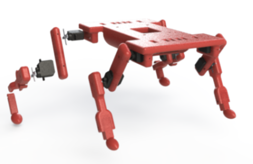
The Foxbot we built was loosely inspired by the red fox. We designed a flat body to hold the battery pack and Arduino Uno, as well as simple limbs with football shaped feet. The front limbs were made of two sections, while the rear limbs were made of three, with the bottom section left unactuated but connected by a rubber band. This mimicked the structure of a fox’s limbs while allowing us to stay within the allowed number of servos; it also provided compliance, although we didn’t have the knowledge to make proper use of this.
The entire body was 3D printed out of ABS, with the servo motors serving as joints. This provided some challenges: the feet - made of plastic, turned out to be too slippery to grip the floor properly, but we coated them in rubber and this provided adequate performance. The servo motors also proved a problematic point, since the weight of the robot placed a bending load on their axles. The motors weren’t designed to handle bending loads, so this setup resulted in limb displacement and eventual failure for most of the servos.
Gait
Based on a heuristic analysis of some videos of the red fox’s gait, we came up with the gait diagram shown below. This is a dynamically stable gait, with two legs lifted off of the ground for the majority of the gait cycle, which is a challenging motion to produce. Based on the project guidelines, we decided to first try a statically stable gait, even though the fox doesn’t use one, and then try to transition to a dynamic gait if we were successful.

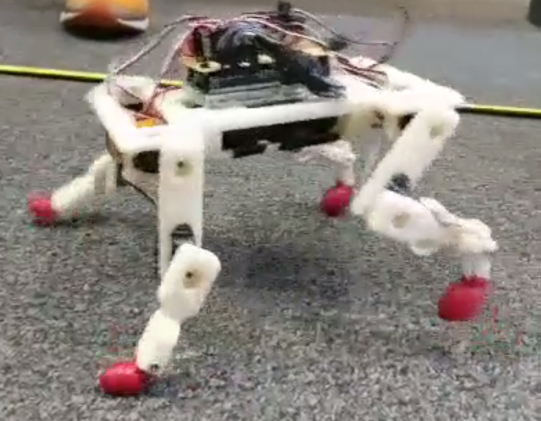
The gait that we eventually developed was dynamically stable, but developed entirely heuristically based on an attempt to produce reasonable joint trajectories. The motion seems reasonable, based on the video below, but the lack of sensing was the fundamental challenge to this project. We struggled to reach the desired travel distance because the robot would veer sideways due to a combination of servo asymmetry and environmental factors that we had no way to measure or correct. This effect is clear in the video.
Attribution
This work was done as a final project for ENME489L - Bio-Inspired Robotics, taught by Dr. Hugh Bruck and Dr. Ryan St. Pierre at the University of Maryland, College Park in Fall 2016.